
Circuit diagram of common Anode RGB LED with Arduino Arduino code for common Anode RGB LED with Arduino int red=3 Ĭircuit diagram of common Cathode RGB LED with Arduino Arduino code for common Cathode RGB LED with Arduino int red=3 Ĭreate variables for defining the pins of Arduino UNO where you have connected the pins of RGB LED. It will also work in the same manner as that of the common anode RGB LED.īy directly applying a voltage to both the types of LED you can get the RED color, BLUE color, GREEN color, a combination of RED and BLUE color, a combination of RED and GREEN color, a combination of BLUE and GREEN color, and a combination of all the three colors. Then to light up the RED color, connect the RED color terminal to the positive terminal of the power source. To light up a common cathode RGB LED, you have to connect its common terminal to the negative terminal of the power source. You can also light up two or all three colors simultaneously, then you will get different color combinations. Then to light up the RED color, connect the RED color terminal to the negative terminal of the power source. To light up a common anode RGB LED, you have to connect its common terminal to the positive terminal of the power source.

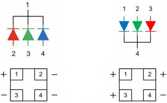
Forward current: RED color – 20mA, GREEN color – 20mA, BLUE color – 20mA.Forward voltage: RED color – 1.8 to 2.2 V, GREEN color – 3.0 to 3.4 V, BLUE color – 3.0 to 3.4 V.We call it a common cathode RGB LED because in this type of LED, the anode terminal of all three LEDs is shorted internally and connected to one terminal and that terminal is known as a common anode terminal. On the other hand, a common cathode RGB LED also consists of four terminals but in this type of RGB LED one terminal is for the common cathode, one is for the RED LED anode terminal, one is for the GREEN LED anode terminal and the last one is for the BLUE LED anode terminal. We call it a common anode RGB LED because in this type of RGB LED, the anode terminal of all three LEDs is shorted internally and connected to one terminal and that terminal is known as a common anode terminal. A common anode RGB LED consists of four terminals out of which one is for the common anode, one is for the RED LED cathode terminal, one is for the GREEN LED cathode terminal, and the last one is for the BLUE LED cathode terminal. One is a common anode RGB LED and the other is a common cathode RGB LED. The RGB LED that we gonna discuss in this article is non-programmable and it is of two types. One for the RED color, one for the GREEN color, and one for the BLUE color. In other words, it’s a single LED that contains three LEDs inside it. Smaller values will draw more supply current when the N-chan MOSFET is on, larger values are more susceptible to noise when the N-chan MOSFET is off.The RGB LED is a type of LED that can produce three main colors that are RED, GREEN, and BLUE. You can probably get away with anywhere from 1k up to 100k. Resistor values were chosen semi-arbitrarily. Here's a basic example which uses a P-chan MOSFET to drive the LED's, and a N-chan MOSFET/pullup resistor to control the P-chan MOSFET: (again, ignoring any LED current limiting schemes)
Common anode cathode led series#
If your micro is not able to achieve either of these levels, you can use a second transistor to drive the transistor in series with the LED(s). Alternatively, if you have use an up-stream P-Chan MOSFET, your control signal will need to be at least the level of the source voltage to turn the LEDs off (this is the MOSFET pin source voltage, not supply voltage). If what you want is to control individual LED's, then you might still be able to use an N-Chan MOSFET, but your control signal will need to be at least Vthresh above the source voltage to turn the LEDs on. Simulate this circuit – Schematic created using CircuitLab Here's an example circuit, ignoring LED current limiting schemes for now.

If all you need is to turn all the LEDs on/off using PWM, you can attach the N-chan MOSFET between the common cathode and ground.


 0 kommentar(er)
